
Building a CAN Data Logger for Test Monitoring
Monitoring the CAN Bus, decoding its signals, and logging the data to S3
This is the second in a series on test & measurement automation using Flojoy and CAN data.
See Part 1 for an explanation of how the CAN bus protocol works and is being used. In this article, we will cover reading CAN data from Flojoy and the different possible ways to log CAN data.
Goal
Now that we know how the CAN protocol works, let's capture real data of a system at the same time that we are conducting a temperature test. We would also like to be able to log this data in a way that is easily shareable with our team!
Setup
Flojoy
To make it easy, let's use Flojoy, the modern test and measurement app that uses Python. We will be able to easily drag and drop the necessary blocks to conduct this test, and if needed, we could easily create our own block in Python to extend the capability.
Hardware
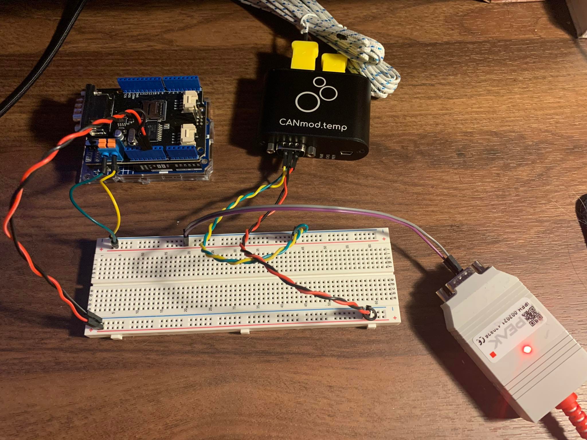
For this test, we'll be using the PEAK-USB, a CAN interface for USB that allows us to easily plug it into a CAN system to capture the information transmitted on the network. We're particularly interested in temperature data over time. I've installed a CANmod.temp on a CAN bus system, which will log the temperature of multiple thermocouples every second. For simplicity, our goal is to acquire only this data.
Here is the list of today's goals:
Connect the PEAK-USB, to Flojoy
Acquire CAN data
Filter the data
Discuss how to log this data (Flojoy Cloud)
Reading CAN bus data from Flojoy
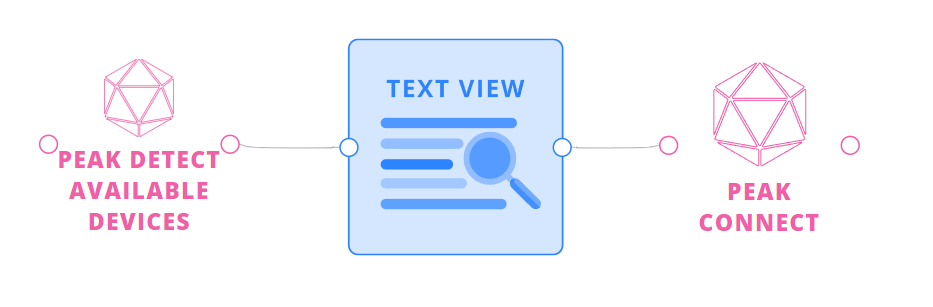
First of all, let's connect our PEAK-USB to our computer and to Flojoy. To do that, we'll need to install the PEAK driver. Then, we'll be able to connect to it in Flojoy:
Note: I'm using the PEAK-USB, but any CAN-USB device will work with all the Flojoy blocks. The only step you need to take is: 1. Determine if your device needs a driver and which CAN interface it is using. 2. Use the right CAN_CONNECT block with it. If this block doesn't exist yet, let us know and we will be happy to create it, or try it yourself by examining how the other connect blocks are made. More explanations are in annex!
Once the connection is established, let's read some messages from the CAN bus!
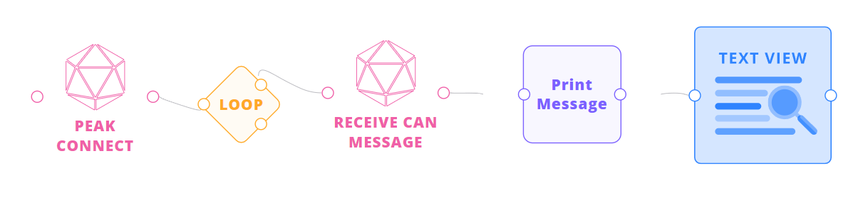
The first thing you will notice is that there are a lot of messages on the bus, and we are only interested in the ones from the thermocouple. With the system I'm using, I know that the message ID I'm looking for is 0x01, so I'll apply a filter on the ID directly at the CAN Controller level of the CAN-USB device. This way, our computer won't be busy reading all the messages, but only the ones from the sensor.
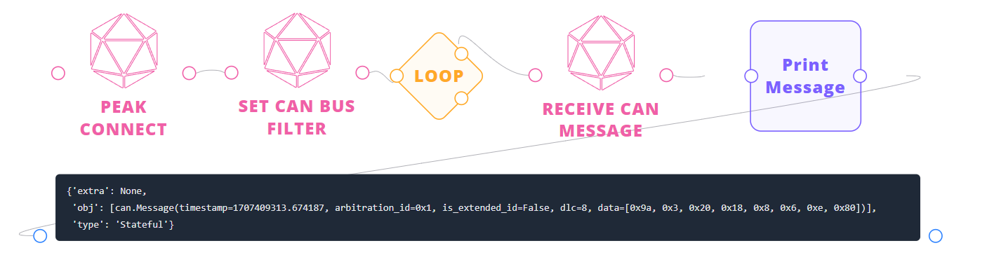
Note: Not all CAN-USB devices support kernel-level filtering. If this is the case for your device, apply a FILTER_CAN_MESSAGE_BY_ID block after the RECEIVE_CAN_MESSAGE block.
Data storage and decoding
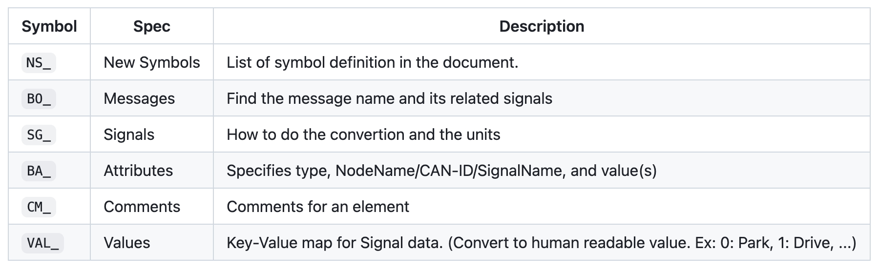
It's easy to think about CAN message as and ID + Message, but, for the most part, this data is unreadable and useless for human in its raw form since we don't know how to interpret it. For this reason a semi-standard was developed which is .dbc files. I like to thing of them as a big ID lookup table which will convert a message like:
ID       Data
0x1      99 03 20 17 08 06 0E 80
To:
Message  CJTemp  TLStatus   TLTemp  TRStatus  TRTemp
ABC      25      Err3       0       OK        32
Every company developing CAN bus systems has one, and it's often kept private, but a lot of people spend countless hours on reverse-engineering them. The structure of a .dbc file goes as follows:
With the syntax of a signal from a message:
BO_ <CAN-ID> <MessageName>: <Length> <Transmitter>
    SG_ <Mnemonic> : <Start>|<Length>@<BOM><Sign> (<factor>,<offset>) [<min>|<max>] "[unit]" [Receivers]
Where:
Mnemonic: Unique name identifierStart: Start bit of the signalLength: Total signal length in bitsBOM: 1 for little-endian and 0 for big-endianSign: + for unsigned and - for signedfactor: Decimal number to be multiplied by the signal valueoffset: Decimal number to be added to the signal valuemin|max: Min and max value relative to factor and offsetunit: String representation of the signal unitReceivers: Consumer list (BU_)
With that in mind: let's do an example for our sensor with the previous message:
BO_ 1 Thermocouple: 8 Vector__XXX
SG_ CJTemp : 0|8@1+ (1,-128) [-20|85] "degC" Vector__XXX
...
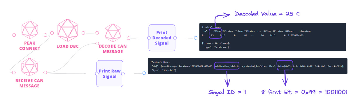
CM_ SG_ 1 CJTemp "Cold junction temperature";# First 8 bits (0x99) * scale + offset
CJTemp = 0b10011001 * 1 - 128
print(CJTemp)
>>> 25And by looking at the comment for the signal and the unit, we know that the cold junction temperature is at 25°C.
For a better user experience, let's directly do all that in Flojoy!
CAN data logging
To log all the data from the CAN bus device, there are various options available. The ASAM Measurement Data Format (log.mf4) immediately comes to mind, offering a binary format ideal for storing CAN recorded data for post-measurement processing and long-term storage.
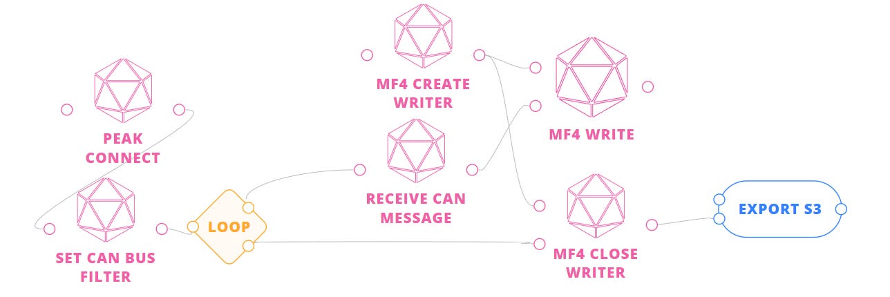
While this format and storage method would be advantageous for exporting large quantities of data to an AWS S3 bucket, our current focus lies more on post-processing and share-ability aspects that an S3 bucket does not cater to. Instead, let's decode the messages and send the bulk result to the Flojoy cloud!
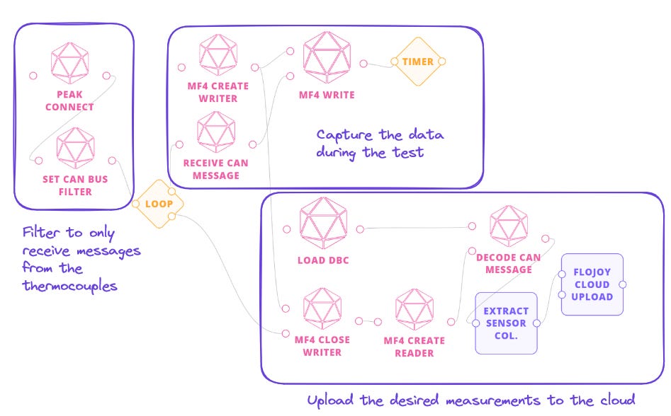
Furthermore, let's incorporate some logic to report the test results.
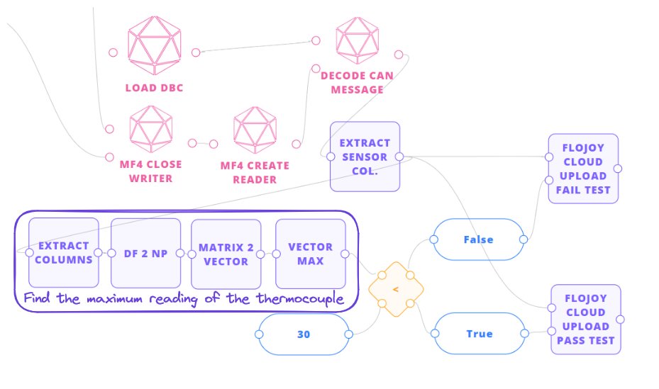
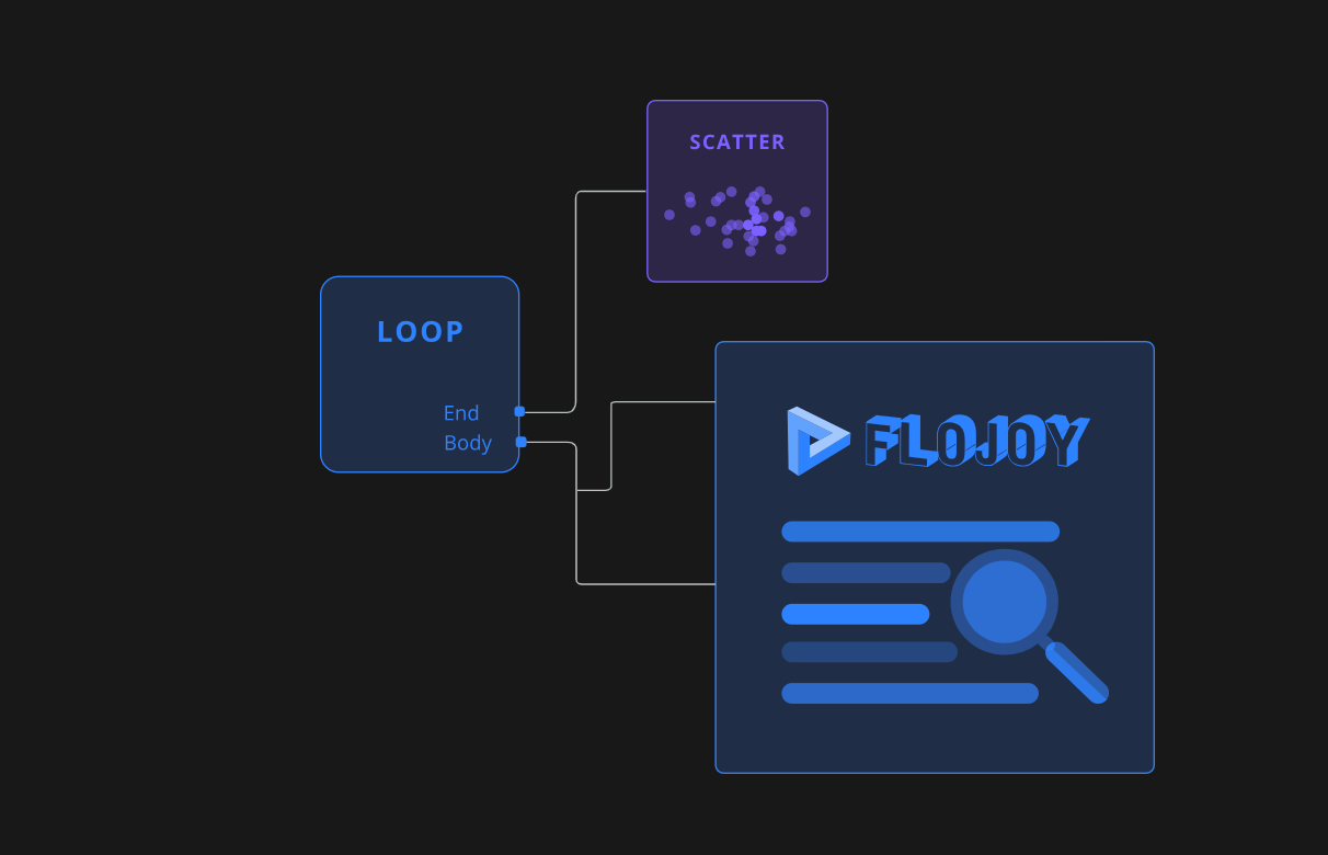
This approach allows us to easily visualize and share the test results with our team, and even conduct further analysis by importing the data elsewhere directly from the flojoy_cloud python API! Just be logging in at cloud.flojoy.ai we can see our test results:
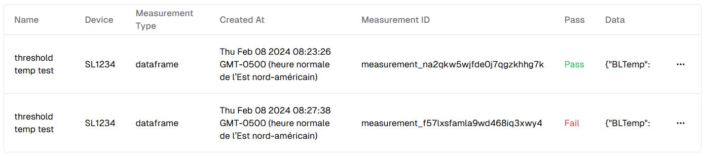
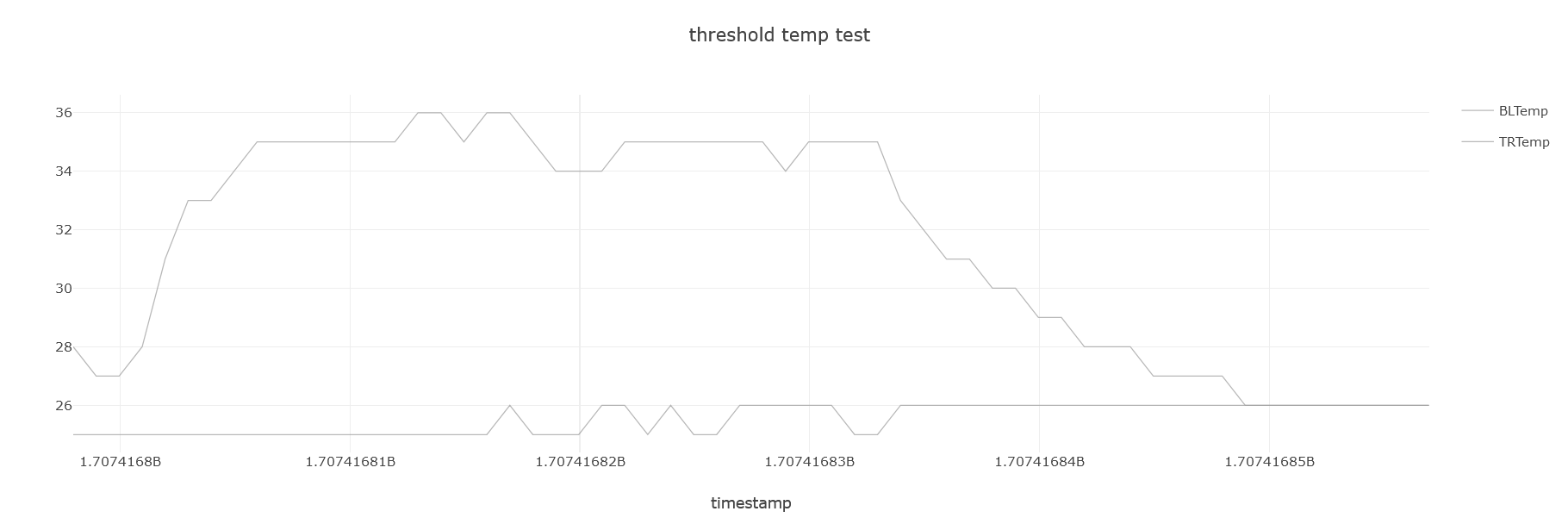
Incorporating Flojoy Cloud into our data logging and analysis workflow adds significant value. With Flojoy Cloud, we gain the ability to easily share and visualize our sensor results, enabling quick iterations on design improvements or monitoring large-scale production processes!
Wrapping up
In conclusion, this article has outlined the process of logging CAN data for analysis, focusing on the utilization of Flojoy and CAN interfaces. We've discussed the setup, including connecting hardware such as the PEAK-USB, reading CAN data, filtering messages, and decoding them using .dbc files. Additionally, we've explored options for data storage and discussed the benefits of utilizing Flojoy Cloud for sharing and post-processing. By following these steps, users can efficiently capture, interpret, and share CAN data, facilitating informed decision-making and collaborative analysis within their teams.
Appendix
How to connect to any CAN interface in Python and convert the code to a Flojoy block
Flojoy uses Python-can under the hood, an open source library that allow a user to use the same function for message manipulation for different type of CAN-USB driver. The Flojoy docs have a section showing how to create a Block. In our case, the PEAK-USB driver allow us to use the pcan interface to interact with the device. Knowing that we can easily connect to our device in Python:
First, let's install the library and the extension for pcan:
pip install python-can[pcan] And after let’s connect to it
import can

# Find the device address
available_channels = can.detect_available_configs("pcan")
print(f"Available devices: {available_channels}")
PCAN_address = available_channels[0]

# Connect to the device
connection = can.interface.Bus(interface="pcan", channel=PCAN_address, bitrate=bitrate)

# Read a message from the device
connection.recv()
Now that it works, let make it compatible with Flojoy
from flojoy import flojoy, DataContainer, DeviceConnectionManager, HardwareDevice
from typing import Optional
import can

# This will automatically install the library
@flojoy(deps={"python-can[pcan]": "4.3.1"})
def PEAK_CONNECT(
    PCAN_address: str,
    bitrate: int = 500000,
    default: Optional[DataContainer] = None
) -> Optional[DataContainer]:

    # Create the connection with the device
    session = can.interface.Bus(
        interface="pcan",
        channel=PCAN_address,
        bitrate=bitrate
    )

    # This is a Flojoy object that allows you to store
    # the connection and retrieve it in other blocks
    DeviceConnectionManager.register_connection(
        HardwareDevice(PCAN_address),
        session
    )

    return None
Congratulation, you just made your first Flojoy block!